
First and foremost: CO2 Indicator
1. First, in your CO2 kit you purchased, there should be a C02 indicator.
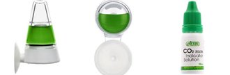
Figure 1. CO2 indicator and CO2 indicator solution
2. Regardless of the shape and size of the CO2 indicator, there is a faint line/ mark that
indicates how much CO2 indicator fluid/solution needs to be added.
3. Separate the Perspex half from its white base plate, which the suction cup attaches to, and invert the Perspex half so that it is in a ready–to–fill position.
4. Add enough such that the fluid level(meniscus) touches the line.
5. Pop the Perspex half back on in its inverted position and gently upright the CO2 indicator in the position shown in Figure 1. (For all–angle CO2 indicators, quickly invert the indicator).
Still confused?
YouTube links:
CO2 indicator
All–angle CO2 indicator
Setting up your CO2 System

Figure 2. Examples of CO2 Systems
1. Regardless of the setup (i.e., pH controller regulated, or timer regulated), screw the
regulator onto the threaded outlet connection of the CO2 bottle. (At this stage, do not turn on the main valve of the CO2 bottle! Also, ensure that the needle valve is closed as well).
**Ista’s disposable CO2 systems do not have main valves—there is only a needle valve**
2. Now, below the needle valve should be a nut that screws onto a 4mm barbed nipple; on the regulators with inbuilt bubble counters, this part can be seen on top of the bubble counter.
3. Using the 4mm clear pipe you have been provided, cut the length of pipe to the desired length (60cm to 100cm should be more than sufficient in most cases). Somewhere along the desired length of the pipe, install an inline stainless steel check valve (systems with inbuilt bubble counters already have a check valve).
4. Now, unscrew the nut off the regulator to reveal the 4mm nipple. Thread the removed nut through the length of the pipe connected behind the check valve to the 4mm (i.e., behind the arrow displayed on the barrel of the check valve). Then, connect said pipe to the 4mm nipple and then screw the nut back in its place to tighten the 4mm pipe–to–nipple connection.
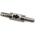
Figure 3. Check valve
5. For the other section of the pipe (i.e., the pipe connected to the check valve in front of the arrow displayed on the barrel of the check valve), connect a CO2 diffuser to the end of the pipe and place it in the desired position in your tank (preferably an area of high flow—the longer the microbubbles produced by the diffuser stays in the water, the more efficiently the CO2 diffuser will dissolve into the system. If you have an inline atomiser/diffuser, or if you have an inline reactor, the only difference is that the 4mm pipe is connected to the inline unit, which is connected somewhere along the length of your filter canister’s return pipe.
6. Then, coming out of your CO2 regulator ‘s solenoid (a valve which regulates when CO2 is added to your tank) should be a power cable, simply plug this to your timer connected to the nearest wall socket/ power point, or pH controller—there should be a box connected to the pH control console with a single power point. You can turn on the solenoid.
7. But ensure that everything is off at this point, CO2–wise (i.e., the needle valve and main valve of your CO2 system).
Setting up your pH controller or bubble-counter regulated system
If you have a pH controller,
1. Take out the two calibration solutions from the pH controller box—one contains an orange fluid, another contains a green fluid—now, connect the pH probe to the pH control console. Don’t plug the power cable to the wall socket just yet.
2. On the control console, there is a switch that allows you to connect to one of two modes: “pH” or “SET”.
3. Set to “pH”
4. Get ready the two solutions in front of you as well as a container filled with tap water and a few tissue papers. Also, get out the calibration screwdriver from the pH controller box
5. Now, remove the pH probe from its storage container and place the probe in the container of water.
6. Plug the pH controller console power cable to the wall socket.
7. There should be a reading that appears on the control console (it doesn’t matter what the reading is), take the probe out of the container filled with tap water, then lightly wipe the pH probe—it doesn’t have to be bone dry.
8. Put the probe in the pH 7 solution (green).
9. Wait for the pH reading on the control console to stabilise. Once the reading has stopped fluctuating, use the calibration screwdriver, and insert it into the adjusting screw located in the hole below “pH 7” displayed on the control console. Turn anticlockwise or clockwise until the reading on the control console reads 7.00.
10. Then, remove the probe, place it in the container of tap water.
11. Take the probe out of the container filled with tap water, then lightly wipe the pH probe—it doesn’t have to be bone dry.
12. Put the probe in the pH 4.01 solution (orange).
13. Wait for the pH reading on the control console to stabilise. Once the reading has stopped fluctuating, use the calibration screwdriver, and insert it into the adjusting screw located in the hole below “pH 4” displayed on the control console. Turn anticlockwise or clockwise until the reading on the control console reads 4.01.
14. Calibration is done! Now, you can place the probe into the tank
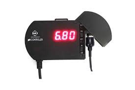
Figure 4. pH controller control console
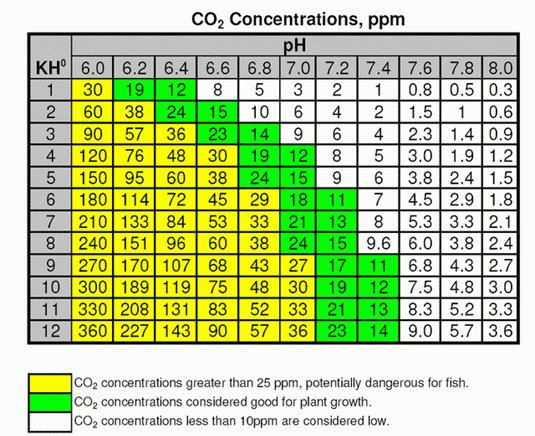
Figure 6. pH-kH CO2 Chart
15. Using the chart in figure 6, find out the ideal pH you need to set your pH controller to. For example, if you have a KH of 3, then set the pH between 6.8 to 6.6; in this case, we recommend starting from 6.8 or, if you want to be cautious, you can set it at a higher pH level (e.g., 7) and work your way down. If you don’t know what kH is, read our water quality handout or ask a staff member.
16. Switch to “SET”. To adjust to the desired pH, below “SET” there is a hole where there is a screw that can be adjusted by the calibration screwdriver. Using the screwdriver, turn anticlockwise or clockwise until the desired pH has been reached. Now, switch back to “pH”.
17. OKAY, now you can turn on the main valve (all the way) and, for the needle valve, crack it open ever so slightly! Patience is a virtue! Fine bubbles coming out of the diffuser is what you want to achieve! Now, the waiting game, watch the colour of the CO2 indicator change to green (may take an hour or two).
18. IMPORTANT: The CO2 indicator you had setup earlier will tell you whether you are dosing too much or too little: if the fluid of the CO2 indicator is blue, the pH you have set is too high; if the fluid of the CO2 indicator is yellow, the pH you have set is too low; if the fluid is green, then that means no change needs to be done.
19. You are done! There is nothing else to do. Always leave the system on (i.e., don’t turn it off at night). Also, you don’t aerate the tank at night.
If you have a timer,
1. Set the timer to turn on the solenoid (i.e., open the valve to release CO2 into the tank) 1hour before the lights turn on, and set it to turn off one hour before the lights turn off.
2. Then, fill the bubble counter with bubble counter fluid.
3. Okay, turn on everything! turn on the main valve (all the way) and, for the needle valve, crack it open ever so slightly! Patience is a virtue! Fine bubbles coming out of the diffuser is what you want to achieve! Now, the waiting game, watch the colour of the CO2 indicator change to green (may take an hour or two or three). Be at home at all times during the setup, you don’t want to gas your fish!
4. Start off slowly: start off with 30 bubbles per minute (*note* this depends on the size of the tank!) if you have a 60-litre tank. However, this is just a guide, it does not necessarily mean that for a 600L tank you need 300 bubbles per minute, please ask a staff member for help before blasting your tank with CO2!
5. Wait one hour, if it turns green, great! If it is still blue, consider increasing to 45 bubbles per minute. Increase it to 60 per minutes if that is not enough, and so on and so forth until you get green. Trial-and-error is boring, but it is worth the wait. Take your time. What you want to achieve is green CO2 indicator fluid one hour before the lights turn on, and you want that green to remain green for the duration of the photoperiod (you should leave your light on for 6-8 hours)
6. IMPORTANT: The CO2 indicator you had setup earlier will tell you whether you are dosing too much or too little: if the fluid of the CO2 indicator is blue after 1 hour and remains this way for the whole photoperiod, the number of bubbles per min is not enough; if the fluid of the CO2 indicator is yellow, the number of bubbles per min is too much regardless of how long it takes; if the fluid is green after 1 hour but turns yellow in 2 hours, reduce the bubble count a little; if the fluid is green after 1 hour and remains this way for the whole photoperiod, then that means no change needs to be done ( this is in an ideal world). Let us know if you have any further questions
7. Okay, once you have followed all the steps, you are done!